- ALL COMPUTER, ELECTRONICS AND MECHANICAL COURSES AVAILABLE…. PROJECT GUIDANCE SINCE 2004. FOR FURTHER DETAILS CALL 9443117328
Projects > ELECTRICAL > 2017 > IEEE > POWER ELECTRONICS
With ever increasing demand of feature-rich portable electronics, Single-Inductor Multiple-Output (SIMO) converters are becoming a cost-effective option to provide different supply voltages while maintaining long battery life. A single-discharge (SDC) control scheme is proposed to simplify the SIMO design, to achieve low cross regulation, and to support wide range of loads with reasonable power efficiency. A SDC SIMO buck converter with 4 outputs composed of comparators, phased-locked loop, finite state machine (FSM) controller, and an output stage, is prototyped using TSMC’s 0.18 μm BCD process. In addition to the basic switching functions, the FSM controller provides a state skipping feature to allow no-load regulation.
Current-Mode Single-Inductor Multiple-Output (Simo) Boosting Buck Converter.
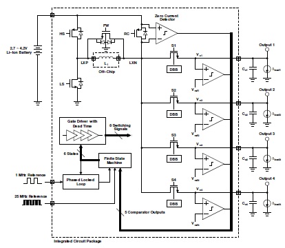
A SDC SIMO converter is proposed and designed using a simple set of circuit blocks. The converter is made up of a latched comparator, FSM controller, PLL, gate drivers, and an output stage. The proposed converter design regulates 4 outputs with output voltages of 1, 1.2, 1.5, and 1.8 V. Each output support nominal load current of 33, 50, 50, and 70 mA, respectively. The overall functionality of the prototype is verified using fabricated die. Unlike many of the previous designs, it can regulate outputs from no load all the way up to the rated load. The load transient response across a wide range of load is also verified. In this paper, a Single Discharge Control (SDC) SIMO converter is proposed to provide low cross-regulation for a wide range of loads. The SDC SIMO converter with 4 outputs, is an extension to the fully hysteretic converter. It operates in two main phases, where the first phase charges each output individually until their voltages reach the required reference voltage. Unlike previous works, all outputs are charged during the rising inductor current waveform. This is done by guiding current from the high-side switch (HS) through inductor L1 to output switches S1 to S4. Once the outputs are charged, the converter enters the second phase, where a recycling switch (RC) and the low-side switch (LS) turn on to direct inductor current back into the input battery. Since SIMO converters are common in mobile applications, the reverse current would re-charge the battery and/or the input decoupling capacitor, ultimately recycling the energy. The duration of this recycling phase is determined by the PLL which tries to align the overall switching signal (HS), to be in phase with the 1 MHz reference clock.
Proposed 4-output SIMO with Single Discharge Control (SDC)