- ALL COMPUTER, ELECTRONICS AND MECHANICAL COURSES AVAILABLE…. PROJECT GUIDANCE SINCE 2004. FOR FURTHER DETAILS CALL 9443117328
Projects > ELECTRONICS > 2019 > NON IEEE > EMBEDDED SYSTEMS
This paper is about charging E-vehicle module using the Solar panel, availability of maximum power is viewed by IOT device and the maximum power generated by the solar is being tracked using the MPPT controller. The simulation model is designed using Proteus software. The whole setup is connected to the Arduino UNO R3, the battery level, generated and distributes an amount of the battery is viewed using an LCD. GSM modem is used to get an alert message for any reduction of power occurred in the system. A web page is used to check the availability status of charge, the amount of power transferred to the charging module and the available location for the charging station can be displayed. The main idea of this paper is to reduce greenhouse gas emission and fossil fuel.
Battery monitoring in smart grids, IOT based transformer monitor
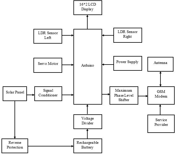
As a solar PV array plays a vital role in a project, the model simply uses torches with LDR sensor to track the position for generating power from the source which helps the continuous flow of energy. Since the tilting angle of the sun varies from 0o to 180o, two sensors should be built for either direction i.e., one in the left and other in the right. Then, the collected electric source from the PV cell is transferred to the converter together with the buck regulator which stabilizes the power.The entire DC-DC converter setup maintains the reliability of output from the cell and it should unbiased output when it exceeds the expected result in order to avoid a hysteresis loss. Initially, DC-DC converter accepts the DC input voltage and also provide s output as DC voltage in next level whether lower or higher depends on the requirement such that converter output voltage matches the power supply required to the module. The regulated constant voltage is delivered to an analog input of Arduino to avoid the complexity of the operation. The meter should help to monitor the constant voltage. Arduino UNO R3 is a microcontroller board with 20 digital input and six can be used as an analog input. Program for tracking, delivering and displaying the required power output supply can be loaded on it as follows from the easy-to-use Arduino computer program.
BLOCK DIAGRAM